

Remote transformer protection (RTP)
RTP is Synaptec’s protection for transformers far from any substation.
RTP gives unit protection to a transformer far from any substation, with your choice of 87T relay running its own settings. The transformer site needs only standard CTs, passive sensors, and a single fibre back to the substation.
RTP is part of Reflex, Synaptec’s range of ultrafast protection for complex and remote circuits and assets, and runs on Distributed Electrical Sensing (DES).
Get in touch

Aneesh Chandran
Sales Engineering lead

Prasanta Das
Regional Sales Director - India & Gulf States

Dr Oyedotun E. Oyewole
Sales Engineer
The industry challenge
Many transformers sit well away from any substation: step-down units on mid-route taps, supply points for mines and pumping stations, and transformers at the landing points of island links. Without a substation of their own, they rarely have unit protection. They rely on time-graded overcurrent protection from the feeding end and on mechanical devices such as Buchholz and pressure relief relays, which respond to the consequences of a fault rather than its onset.
Overcurrent protection clears in grading time rather than unit time, and cannot tell a line fault from a transformer fault. The longer an internal fault persists, the more likely the transformer needs replacing rather than repairing, and replacement lead times for large transformers now run to years. Where remote sites have been connected at all, it has usually been over pilot wires or telephone circuits, which are now being withdrawn.
The two conventional options
| Accept slow clearance | Build infrastructure at the transformer |
|---|---|
| Faults cleared in grading time rather than unit time | Relay, panel, auxiliary supplies, and batteries at the transformer |
| Fault damage increases with clearing time | A new communications channel to the site, fit for protection |
| Line and transformer faults cannot be told apart at the feeding end | Testing and maintenance visits for the life of the scheme |
| Transformer replacement lead times measured in years | Civil works to house the equipment at a site with no building |
Our solution
RTP forms three differential zones from one set of passive sensors, all measured at the feeding substation. Zone 1 covers the HV line from the feeding substation to the transformer HV terminals. Zone 2 covers the transformer from its HV to LV terminals, with a neutral CT for restricted earth fault protection. Zone 3 covers the LV line to the receiving substation. The DES Interrogator runs line differential protection (87L) on Zones 1 and 3, using the same element as MCP, and identifies which zone a fault is in, so auto-reclose can proceed for a line fault. The transformer zone runs in your choice of 87T relay, which receives the HV, LV, and neutral currents as IEC 61850-9-2 Sampled Values and blocks auto-reclose for a transformer fault. Your main and backup protection remain conventional relays.
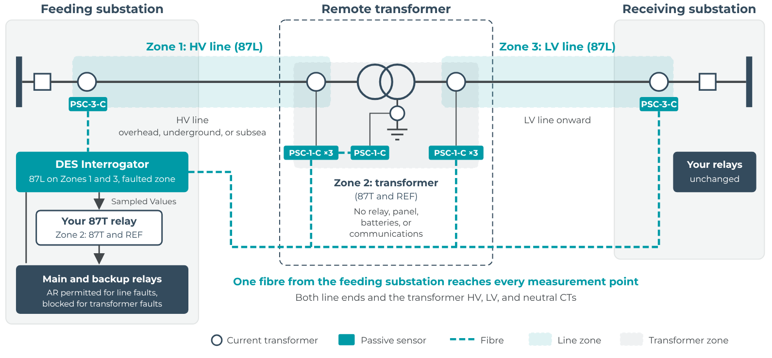
Three zones from one fibre: the line zones in the DES Interrogator, the transformer zone in your chosen 87T relay
How it works
At the transformer
Single-phase PSC-1-C sensors, rated IP68, connect to the secondaries of standard CTs: three on the HV side, three on the LV side, and one on the neutral. They are spliced into a spare fibre and need no further attention.
In the feeding substation
The DES Interrogator reads every sensor over the fibre on a common time base and runs line differential protection on Zones 1 and 3. For a fault in either line zone it allows auto-reclose. It also publishes the transformer’s HV, LV, and neutral currents to the process bus, from which your 87T relay runs Zone 2 exactly as it would from a conventional merging unit and blocks auto-reclose for a transformer fault. Your main and backup protection remain conventional relays.
At the receiving substation
Three further sensors on the existing line CTs complete Zone 3. The relays in the existing panel are unchanged.
Protection functions
| Function | Zone | Runs in |
|---|---|---|
| Line differential (87L) | Zone 1, HV line; Zone 3, LV line | DES Interrogator |
| Auto-reclose permitted for line faults | Zones 1 and 3 | DES Interrogator |
| Transformer differential (87T) | Zone 2, HV to LV terminals | Your 87T relay (Sampled Values) |
| Restricted earth fault | Zone 2, using the neutral CT | Your 87T relay |
| Auto-reclose blocked for transformer faults | Zone 2 | Your 87T relay |
| Faulted zone indication and synchronised fault records | Every measurement point | DES Interrogator |
| Main and backup protection | Feeding and receiving substations | Your relays, unchanged |
Performance
- Accuracy class 1/10TPM to IEC 61869-13.
- Faulted zone identified in under 10 ms.
- All measurements on one time base, synchronised to within one microsecond, with no satellite timing at the transformer.
- Only optical signals beyond the substation fence, immune to electromagnetic interference.
Integration
- The transformer is protected by your chosen 87T relay and its settings.
- IEC 61850-9-2 Sampled Values go to any compliant relay, and GOOSE or dry contacts go into your existing auto-reclose logic.
- Your main and backup protection remain conventional relays, unchanged.
- Site acceptance tests are carried out from the substations, without access to the transformer site.
Where it applies
Rural and island supplies
A step-down transformer on a long line feeding a village, island, or rural network. Faults on either line and in the transformer, including restricted earth faults, are identified separately.
Industrial and infrastructure supply points
Mines, pumping and compressor stations, rail feeder sites, and similar loads supplied from a tap on a transmission or distribution line.
Island links
A subsea cable to a transformer at the landing point, with a line onward into the island network. Cable, transformer, and island-side faults are identified separately, so crews are sent knowing where the fault is.
Shunt reactors
The same arrangement protects a shunt reactor, with a reactor zone in your 87R relay in place of the transformer zone.
Proven in service
MCP and RTP use the same DES Interrogators and passive sensors that Synaptec supplies for protection and cable systems monitoring worldwide. In more than 1.5 million sensor-hours of operation, no Synaptec sensor has ever failed in service. The line zones in RTP use the same 87L element as MCP, which is in service with transmission and distribution operators in India, Europe, and the Middle East.
>1.5 million
sensor-hours of operation (October 2026)
0
sensor failures in service
>60 km
from the substation to the furthest passive sensor
Reflex brochure
The Reflex brochure covers MCP and RTP, how each one works, and the service record of the Synaptec passive sensors and DES Interrogators they share, in eight pages.
Talk to us about your remote transformers
Start with one circuit. Send us the single-line diagram and the fibre route, and we will propose a protection design with a budget price, at no cost. Your preferred contractor or Synaptec’s local partner installs the equipment, and Synaptec commissions it.
Applications


Related posts
The Distributed Mechanical Sensing (DMS) Interrogator
The Distributed Mechanical Sensing (DMS) Interrogator is designed for monitoring of large numbers of point temperature sensors with unprecedented efficiency. The DMS Interrogator allows up to 20 temperature sensors per channel to be multiplexed across up to 8 channels.

Passive Secondary Converter for Current – Three-Phase (PSC3-C) Gen2
The PSC-3-C is Synaptec’s passive, three-phase analogue current sensor for power network applications. It converts Current Transformer (CT) secondary currents into optical signals to be measured, synchronised and digitised over long distances without the need for...
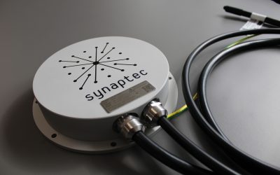
Passive Secondary Converter for Current – Single-Phase (PSC1-C) Gen2
The PSC-1-C is Synaptec’s passive analogue current sensor for power network applications. It converts Current Transformer (CT) secondary current into an optical signal to be measured, synchronised and digitised over long distances without the need for auxiliary power,...
Sectors we support

Power grids

Renewables
