
Case study: Adani Electricity Mumbai Ltd.
Aarey to Borivali 220 kV
Aneesh Chandran | 3 minute read | 16 June 2026
Screen current monitoring on a 220 kV double circuit in Mumbai
Twelve joint bays on a 12.7 km underground double circuit are monitored continuously from one substation, over the fibre laid with the cable. The first data after commissioning showed a bonding defect that no inspection had found, and the operator corrected it during one scheduled visit with no outage taken.
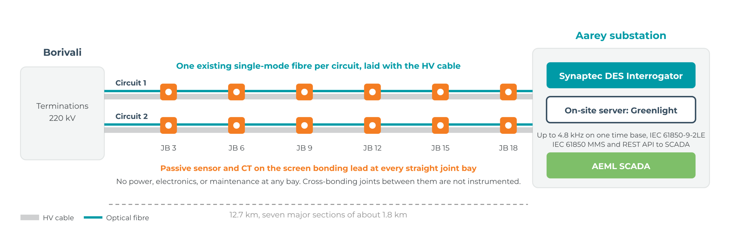
Adani Electricity Mumbai Ltd (AEML) wanted continuous, centralised measurement of screen (sheath) currents on its 220 kV double circuit between Aarey and Borivali substations. Synaptec supplied, through Madhav Engineers Pvt Ltd (MEPL), a Greenlight® screen current monitoring system built on Distributed Electrical Sensing (DES). Passive sensors at 12 joint bays, six per circuit, measure the screen current continuously and report it over a single fibre per circuit to the Aarey substation.
2 months
to pay back the cost of the system, from the first defect found
0
outages taken to find and correct the defect
8.1x
return on investment over the circuit’s remaining 20-year operating life
Adani Electricity Mumbai Ltd is one of India’s leading urban power transmission and distribution companies, supplying electricity to more than three million customers across the Mumbai metropolitan area. Its 220 kV network includes the underground corridor between Aarey and Borivali substations that is the subject of this case study.
Madhav Engineers Pvt Ltd (MEPL), Synaptec’s partner in Mumbai, is a specialist in electrical testing, operations, and maintenance equipment. MEPL supplied and installed the system and is the primary point of contact with AEML.

The challenge
The Aarey to Borivali route runs under the city. Its joint bays sit in manholes under roads, are reached only through confined-space entry, and are waterlogged for months during the monsoon. Manual inspection is slow, disruptive, and hazardous, and a periodic test says little about how a joint behaves between visits. AEML had no continuous view of the condition of its joints, and no way of knowing which bay to open if a problem was suspected.
Screen currents carry the earliest electrical signs of bonding faults, water ingress, and failing joints. The current flowing in the metallic screen at each joint depends on the bonding arrangement, the condition of the link box and earthing, and the state of the insulation. A change in screen current, or a difference between joints that should behave alike, points to a bonding fault, water ingress, or a deteriorating joint long before a failure. Measuring it continuously at every joint bay, and comparing bays with each other, shows which one to open.
The measurement itself set demanding requirements. Each sensor had to cover screen currents from 0 to 400 A in normal operation and up to 12 kA during faults. The monitored joint bays are about 1.8 km apart and up to 11 km from the Aarey substation, with no power or data network at any of them. AEML required time-synchronised, phase-accurate data in accordance with IEC 61850-9-2LE, which conventional fibre sensing cannot meet beyond about 1.6 km without a timing source at each sensor.
The solution
Synaptec designed a Greenlight® screen current monitoring system around AEML’s existing single-mode fibre. At each of the 12 joint bays, a PSC-1-C Passive Secondary Converter is paired with a dual-class current transformer, rated for both measurement and protection, on the screen bonding lead. The PSC-1-C converts the CT secondary current into an optical signal with no power supply, electronics, or data connection at the bay. The six sensors on each circuit share one fibre back to the Aarey substation.
In the substation, a rack-mounted DES Interrogator samples every sensor on one time base, at up to 4.8 kHz. Synaptec’s patented time-of-flight correction keeps timestamps within ±4 μs and phase error below 1° across the full route, so the Interrogator publishes IEC 61850-9-2LE sampled values with no GPS or PTP source at any sensor. Because DES encodes each measurement in optical wavelength rather than polarisation, it is immune to electromagnetic interference along the fibre and needs no paired fibres.
An on-site server running Greenlight subscribes to the Interrogator, stores every measurement, runs the condition monitoring analytics, records full waveforms when an overcurrent event is detected, and makes processed data available to AEML’s SCADA by IEC 61850 MMS and a secure REST API.
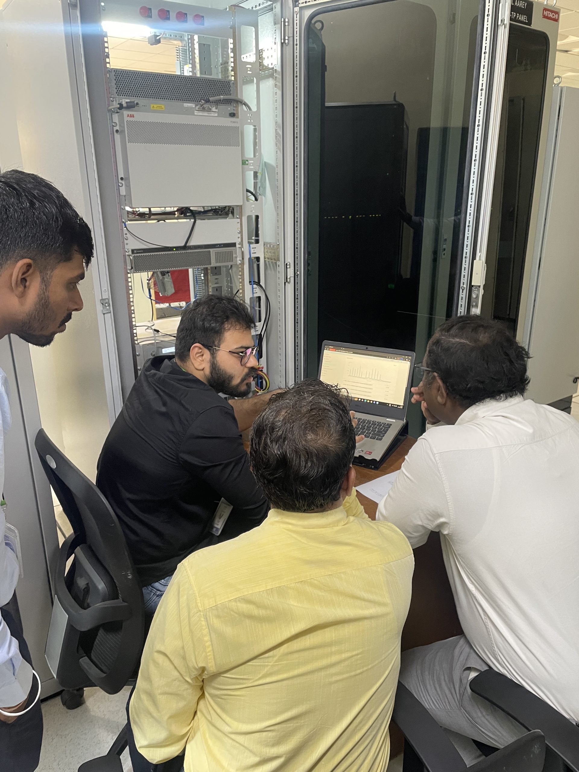
The system was retrofitted to the existing link boxes and bonding hardware with the circuit in service. The DES Interrogator reads up to 30 passive sensors at more than 60 km from the substation, so phase current sensors at the terminations and per-phase screen current sensors can be added without power or communications at the bays. Point temperature at the joints can be added with passive temperature transducers read by a DMS Interrogator.
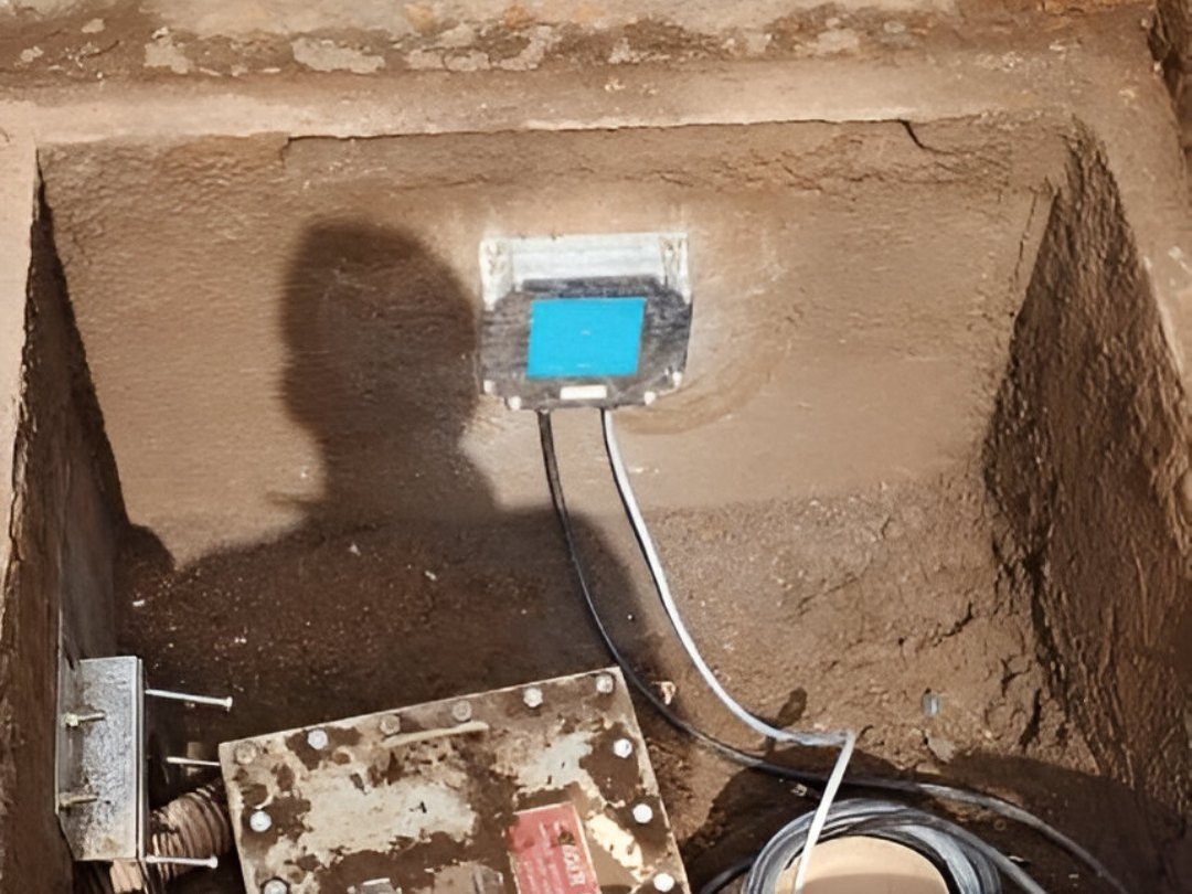
Passive sensor installed in a joint bay on the route
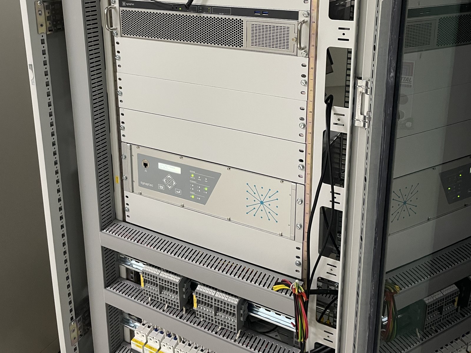
DES Interrogator in the Aarey substation rack
Installation overview
What the first data showed
The first batch of data after commissioning contained two findings. Neither had been seen before, and neither needed an outage or a confined-space survey to find.
Screen current higher on one circuit
At joint bay 3, the median screen current on circuit 2 was about 130 A, against about 70 A on circuit 1 at the same bay and 13 A or less at every other bay on both circuits. Where two identical circuits differ at one location, the cause lies in one of them. The excess was consistent with a high-resistance screen bonding connection at joint bay 1, an uninstrumented bay two sections closer to Borivali.
Elevated zero-sequence current on both circuits
The same bay also showed elevated zero-sequence current, and this one appeared on both circuits. A current common to both circuits points to a source outside either cable. The analysis showed it entering the cable system at the Borivali end and returning to earth through joint bay 3, while joint bay 18 at the Aarey end read close to zero on both circuits.
The recommendation and the outcome
Synaptec’s quarterly data review gave AEML a prioritised inspection plan. The first action was to inspect the screen bonding connections at joint bay 1 on both circuits. The second was to test for sources of zero-sequence injection and harmonics at the Borivali end.
AEML’s maintenance team opened joint bay 1 during a scheduled visit and found a loose, high-resistance bonding connection of the type and at the location the analysis had predicted. It was re-torqued on the same visit. No outage was taken and no repeat visit was needed. The excess screen current on circuit 2 is gone, confirmed by a manual test and by the continuous monitoring.
The elevated zero-sequence current enters from the adjacent operator’s network, so AEML cannot correct it on its own circuit. The monitoring continues to quantify it, which gives AEML measured data for its discussions with that operator.
What permanent monitoring changed
Before the system was installed, AEML’s only view of these joint bays was a periodic inspection, and nothing told it which bay to open. It now has a continuous measurement at every monitored bay, a comparison between the two circuits at each one, and a record of the current entering from the adjacent network. The next anomaly will be seen as it develops.
Discuss the results
Get in touch to arrange a meeting about how Greenlight performed on this circuit and what it would show on yours.
Applications


Related posts
Synthesis® Server
Synthesis® Server provides convenient and secure local hosting of the Synthesis® Core and Visual Core software. It provides a one-box, turn-key solution for collecting and interpreting high-resolution data from many Interrogators, and other data sources. It is...

Synaptec announces million pound sensor system order from Proserv
Unique sensor technology to be integrated into ECG™, Proserv’s holistic subsea cable monitoring system for offshore wind. Synaptec Ltd, the Scottish supplier of passive electrical monitoring systems for power networks, today announced that it has received a...

Passive Temperature Transducer (PTT)
Synaptec’s range of Passive Temperature Transducers (PTT) utilises established, high-performance temperature measurement techniques which are fully compatible with our Distributed Electrical Sensing (DES) technology, enabling remote circuits to be instrumented...
Sectors we support

Power grids

Renewables
